|

Manufacturer of
the World's Finest Mechanical Draft Systems and Kitchen Ventilation Products. |
Enervex Chimney Fans
formerly Exhausto
Model RS Chimney Fan Selection
Wood and Gas Fired Fireplaces and Stoves |
QUICK SIZING.... STEP 1
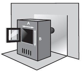
Determine the type of opening, measure and calculate.....
 |
|
 |
|
 |
|
 |
|
 |
|
 |
| One-sided |
|
Two-sided (See-through) |
|
Corner |
|
Three-sided |
|
Free-standing |
|
Free-standing Round |
| A x B |
|
1.5 x A x B |
|
A x B |
|
( A + B ) x C |
|
1.5 x A x B |
|
1.185 x A2 |
|
QUICK SIZING.... STEP 2 |
Determine the type of flue and measure the INSIDE measurement... use the
chart below to convert square and rectangular to round. |
CONVERSION
OF Rectangular /
Square to Round Flues
|
 |
Measure the INSIDE ( side to side ) measurements of the clay liner.
Ex... The INSIDE measurement of 6 x 10"
on a clay liner is equivalent to
10 (dim.
A) - 6 (dim.
B) = 8 (8"
Round)
NOTE: Clay liners are "called"
by their OUTSIDE measurements, the INSIDE measurements may vary
depending on the manufacturer and location.
EX. A 13x13 clay liner may
only have an INSIDE measurement of 10" x 10" |
|
QUICK SIZING.... STEP
3 |
Use of the following fan
selection tables below to calculate the Exhausto fan required to fully exhaust the
fireplace opening and flue system. |
Note: The
RED background
indicates that the fan will most likely create some air-flow noise due to a high
air velocity in the chimney.
The BLUE
background indicates the fan base will not cover the chimney opening and a
special adapter must be used.
| |
Fireplaces (wood-fired) |
| |
Fireplace Opening in square inches |
| Flue
Size |
Max. 400 |
Max. 600 |
Max.
900 |
Max.
1200 |
Max.
1500 |
Max.
2000 |
Max.
2500 |
Max.
3300 |
| 5 |
RS 12 |
RS 16 |
* |
* |
* |
* |
* |
* |
| 6 |
RS 9 |
RS 12 |
RS 16 |
* |
* |
* |
* |
* |
| 7 |
RS 9 |
RS 9 |
RS 14 |
RS 16 |
* |
* |
* |
* |
|
8 |
RS 9 |
RS 9 |
RS 12 |
RS 14 |
RS 16 |
* |
* |
* |
| 9 |
RS 9 |
RS 9 |
RS 12 |
RS 14 |
RS 16 |
RS 16 |
* |
* |
| 10 |
RS 9 |
RS 9 |
RS 12 |
RS 12 |
RS 14 |
RS 16 |
* |
* |
| 12 |
RS 9 |
RS 9 |
RS 12 |
RS 12 |
RS 14 |
RS 14 |
RS 16 |
* |
| 14 |
RS 9 |
RS 9 |
RS 12 |
RS 12 |
RS 12 |
RS 12 |
RS 14 |
RS 16 |
| 16 |
RS 9 |
RS 9 |
RS 12 |
RS 12 |
RS 12 |
RS 12 |
RS 14 |
RS 16 |
| 18 |
RS 9 |
RS 9 |
RS 12 |
RS 12 |
RS 12 |
RS 12 |
RS 14 |
RS 16 |
| 20 |
RS 9 |
RS 9 |
RS 12 |
RS 12 |
RS 12 |
RS 12 |
RS 14 |
RS 16 |
| 22 |
RS 9 |
RS 9 |
RS 12 |
RS 12 |
RS 12 |
RS 12 |
RS 14 |
RS 16 |
| 24 |
RS 9 |
RS 9 |
RS 12 |
RS 12 |
RS 12 |
RS 12 |
RS 14 |
RS 16 |
Check that there are no more than 2x90°
elbows and no more than 30’ of height. If there are more than 2x90° elbows, use
a bigger fan.
 |
The "opening in square
inches" refers to the fireplace or appliances over-all face opening.
Example : In a small wood burning fireplace, if the hearth opening is
18" x 24" with an 8" round ( INSIDE MEASUREMENT ) clay liner in a brick and mortar chimney we
would...
Multiply the length and width, in this case 18" x 24" = 432 square
inches. Being less than 600, on the wood burning chart above, follow the column to the 8"
flue size. Highlighted in
orange, the chart shows an RS 9 to be the proper
size chimney fan for this application. |
Note: The
RED background
indicates that the fan will most likely create some air-flow noise due to a high
air velocity in the chimney.
The BLUE
background indicates the fan base will not cover the chimney opening and a
special adapter must be used.
| |
Fireplaces (gas-fired) |
| |
Fireplace Opening in square inches |
| Flue
Size |
Max. 400 |
Max. 600 |
Max. 1000 |
Max. 2000 |
Max. 2500 |
Max. 3000 |
Max. 3500 |
Max. 5000 |
| 5 |
RS 9 |
RS 12 |
* |
* |
* |
* |
* |
* |
|
6 |
RS 9 |
RS 9 |
RS 12 |
* |
* |
* |
* |
* |
|
7 |
RS 9 |
RS 9 |
RS 12 |
RS 14 |
RS 14 |
* |
* |
* |
|
8 |
RS 9 |
RS 9 |
RS 9 |
RS 12 |
RS 16 |
* |
* |
* |
| 9 |
RS 9 |
RS 9 |
RS 9 |
RS 12 |
RS 12 |
* |
* |
* |
|
10 |
RS 9 |
RS 9 |
RS 9 |
RS 12 |
RS 14 |
RS 16 |
RS 16 |
* |
|
12 |
RS 9 |
RS 9 |
RS 9 |
RS 12 |
RS 14 |
RS 14 |
RS 16 |
* |
|
14 |
RS 9 |
RS 9 |
RS 9 |
RS 12 |
RS 14 |
RS 14 |
RS 14 |
* |
|
16 |
RS 9 |
RS 9 |
RS 9 |
RS 12 |
RS 14 |
RS 14 |
RS 14 |
* |
|
18 |
RS 9 |
RS 9 |
RS 9 |
RS 12 |
RS 14 |
RS 14 |
RS 14 |
RS 16 |
|
20 |
RS 9 |
RS 9 |
RS 9 |
RS 12 |
RS 14 |
RS 14 |
RS 14 |
RS 16 |
|
22 |
RS 9 |
RS 9 |
RS 9 |
RS 12 |
RS 14 |
RS 14 |
RS 14 |
RS 16 |
| 24 |
RS 9 |
RS 9 |
RS 9 |
RS 12 |
RS 14 |
RS 14 |
RS 14 |
RS 16 |
Check that there are no more than 2x90°
elbows and no more than 30’ of height. If there are more than 2x90° elbows, use
a bigger fan.
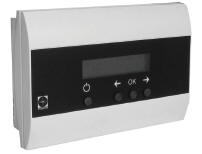
Gas fireplaces will need additional controls...
PDS (Proven Draft Switch) Safety control that senses
a draft. A pressure sensor that ties into the log set or appliance
controls and would shut the gas off if the draft became negative.
EBC10 A pre/post purge control that would extend the
the fan cycle before and after gas is present for a fireplace or appliance.
|
Wood stoves, coal stoves
and fireplace inserts
| |
Stoves |
Fireplace Inserts |
| |
Door Opening in square inches A x B |
| Flue
Size |
Max. 300 |
OVER 300 |
|
6 |
RS 9 |
RS 12 |
| 7 |
RS 9 |
RS 12 |
| 8 |
RS 9 |
RS 12 |
| 9 |
RS 9 |
RS 12 |
| 10 |
RS 9 |
RS 12 |
|
|
Check that there are no more than 2x90°
elbows and no more than 30’ of height.
If there is more than 2x90° elbows, use a bigger fan. |
|
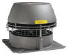
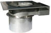
Fan Specifications
|
 |

 |
1 Junction Box
2 Conduit/cord
3 Motor
4 Motor Housing
5 Cooling Plates
6 Bird Screen
7
Base Plate
8
Locking Nut
9
Inlet
10
Axial Vane
11
Hinges
12
Capacitor
( inside J-box )

Capacitor
Wiring Diagram |
|